
The JSCM-7xx is the new generation of safety controllers based on microcontrollers of the Infineon Aurix® family. With this CPU family, available as multi- or single-core, two powerful CPU cores are available for your applications. The used Safety RTOS and the JSCM API allow FS and non-FS applications in the JSCM-720 to run on the same CPU core. This allows simultaneous manual load balancing of the application tasks without blocking the CPU core for FS applications. Once FS applications have been created, they remain untouched and are separated in the system. Combined with agile software development methods, such as SCRUM, the JSCM-720 simplifies and streamlines the development of non-FS software. The application software is conveniently created in C/C++ programming language and transferred via the Jetter diagnostic tool.
The hardware implementation of the JSCM-720 follows the models of the proven JCM-5xx family. The design as central controller with gateway function is also reflected in the I/O configurations: From the high-performance motor control with up to 35 A in the H-bridge to the safety-compliant supply for remote I/O with CAN expansion modules, such as JXM-IO-E3x, numerous I/O constellations can be implemented. Four CAN interfaces and dual port BroadR-Reach 100BASE-T1 complete the concept. Jetter Diagnostic Tooling supports you with wide-ranging functions, even in the field, and lets you create applications in no time.
The JSCM-720 is certified according to the current FS regulations for mobile automation. Certification and the specifications from the Safety Manual enable you to optimally implement the FS requirements resulting from the risk analyses of the devices.
.
| Safety certificates | ISO 13849: PL d; ISO 25119: AgPL c (SRL 1)/AgPL d (SRL 2); IEC 61508: SIL2; Certificates are not yet available at this stage of development |
| Approvals | ECE R10 approval, CE according to ISO 14982 |
| Operating voltage | DC 8 ... 32 V, separate load voltage |
| Protection against polarity reversal | Yes, assuming common reverse polarity |
| Operating/storage temperature | -40 °C … +85 °C |
| Degree of protection | IP65 |
| Vibration | DIN EN 60068-2-64, Cat. 2 |
| Shock | DIN EN 60068-2-64, 30g |
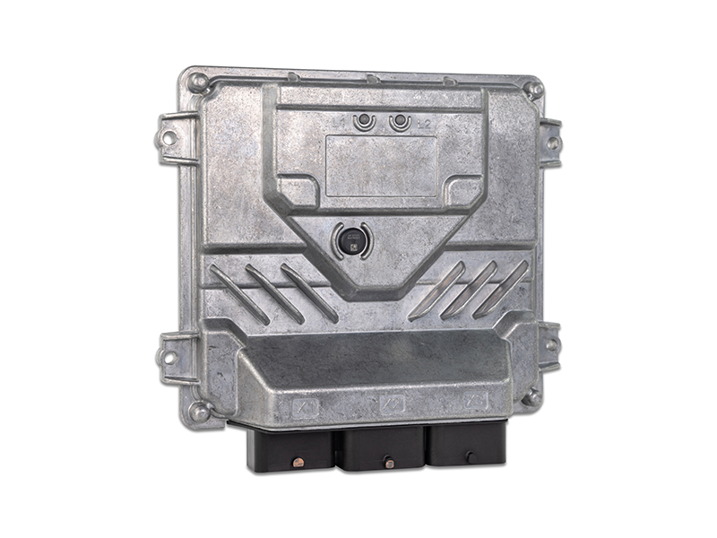
| Housing | Aluminum housing with heat-sink base |
| Dimensions (W x H x D) | Approx. 241 x 211 x 69 mm |
| Operation and diagnostics | Option: 2 dual-color LEDs for diagnostics/operation status/application |
| Connector | CPC 144-pin, Molex |
| CPU | Infineon Tricore Aurix® TC297/TC277 |
| Memory: RAM - Application - Non-volatile | CPU dependent - 2.7 MB internal, 16 MB external - 32 KB EPROM |
| Programming | “C”, FS and non-FS applications can run on one controller |
| Operating system | Certified safety RTOS with JSCM API extension |
| Ports and interfaces | |
| CAN | 4x 125 KB/s to 1 MB/s, CANopen®, SAE J1939, ISOBUS 11783 |
| LIN | 1x 9.6 Kbit/s to 38.4 Kbit/s, LIN-RAW protocol |
| Ethernet/BroadR-Reach | 2x 100BASE-T1 with internal switch |
| Max. amount of inputs/outputs | 104 |
| Sensor supply UBAT | 4, all of them support ratiometric sensors |
| Sensor supply 10 V@100 mA | 2 |
| Inputs | |
| Analog | 8; 0 ... 10 V /0 ... 22 mA, individually configurable, Resolution: 12 bit, input impedance: 50 kΩ, load resistor: 240 Ω; Alternative usage: Digital input for current signal, Fmax: 50 Hz |
| Analog, ratio metric | 4; 0 ... 10 V/0 ... 32 V/0 ... 22 mA/ratio metric input, individually configurable, Resolution: 12 bit, input impedance: 50 kΩ, load resistor: 240 Ω ;Alternative usage: Digital input for current signal, Fmax: 50 Hz |
| Frequency, digital, PNP | 16; Active-high with pull down, input impedance 4 kΩ; Alternative usage: Frequency input, 0.1 ... 20 kHz, pulse time > 20 μs |
| Frequency, digital, NPN | 2; Active-low with pull up, input impedance 4 kΩ; Alternative usage: Frequency input, 0.1 ... 20 kHz, pulse time > 20 μs |
| Frequency, digital, PNP/NPN | 12; Active-high/low with pull up/down (grouped by 4 channels), input impedance 4 kΩ; Alternative usage: Frequency input, 0.1 ... 20 kHz, pulse time > 20 μs |
| Outputs | |
| PWM | 34; 3 A; H-side, PWM 50 Hz ... 1 kHz |
| PWMi | 16; 3 A; H-side, current control 2.5 %; 50 Hz ... 1 kHz |
| PWM PVG | 4; PVG control of Danfoss valves: range 10 ... 90 %, 0=50 %; Alternative usage: 3 A; H-side, PWM 50 Hz ... 1 kHz |
| AO | 2; AO: 0 ... 10 V, 20 mA, 12 bit |
| Half bridge | 8; 8 A; 50 Hz ... 1 kHz, interconnectable as half bridge 8 A; 6 with Fmax 500 Hz blockable to full bridge with 35 A; Alternative usage: 8x PWM 50 Hz … 1 kHz, 8 A; 16x digital outputs, 8 A, high-side; 8x digital outputs, 8 A, low-side |
| Max. permitted total current | 35 A, housing temperature max. +85° C |
| Diagnostic functions | Supply voltage monitoring, total current monitoring, protection against polarity reversal, overload and no-load detection, all I/Os are protected against short circuit to GND and UBAT |
Sales
+49 (7141) 2550-663
sales@bucherautomation.com
Hotline
more
hotline@bucherautomation.com
Further information
(5.17 MB)Catalog "Industrial Automation"
(9.29 MB)Catalog "Mobile Automation"
